
DIY Smart Home Automation Control Your Home with Bluetooth using Android Phone and Arduino

DIY Smart Home Automation Control Your Home with Bluetooth using Android Phone and Arduino

Hi guys, In this tutorial we are going to control home appliances with voice command. You have to just press the google mic button and give command to turn ON or OFF Light. So let’s get started.

For making this project, You will need

  1. Arduino uno,
  2. Bluetooth module (HC-05),
  3. 2 channel Relay module,  (You can use 8 channel relay depends on your project),
  4. Jumper Wire,
  5. Breadboard.

Do connection as shown in diagram.
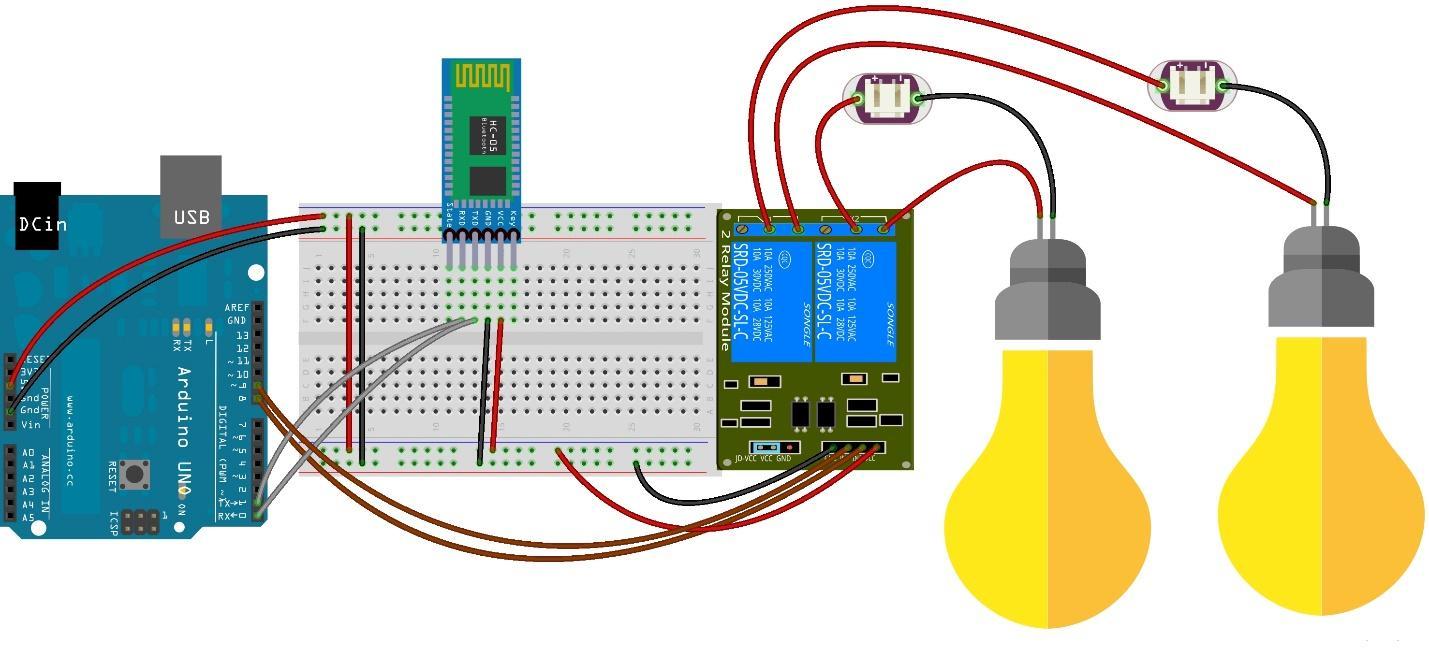
DIY Smart Home Automation Control Your Home with Bluetooth using Android Phone and Arduino

Why we are using voltage divider for Rx pin of Bluetooth module?

Sending data from Tx pin of Bluetooth module required 3.3V, which is accurately given by Bluetooth module.

Problem with Rx Pin in bluetooth

But main problem is with Rx pin, it require 3.3V and we know arduino Tx pin is running on 5V. So we have to use voltage divider in order to reduce voltage to 3.3v. This is the reason I am using two resistor. You can use any combination of resistor for example 1k and 2k ohms resistor, as I am using in this tutorial or you can use 10k and 20k ohms resistor but make sure it should give 3.3V to Rx pin.


Android voice application download

#include <SoftwareSerial.h>

#define BT_RX 0 // Bluetooth module RX pin
#define BT_TX 1 // Bluetooth module TX pin

SoftwareSerial BTSerial(BT_RX, BT_TX); // Create a software serial object for Bluetooth communication

#define RELAY1_PIN 8 // Relay module 1 control pin
#define RELAY2_PIN 9 // Relay module 2 control pin

void setup() {
  pinMode(RELAY1_PIN, OUTPUT); // Set relay 1 pin as output
  pinMode(RELAY2_PIN, OUTPUT); // Set relay 2 pin as output
  digitalWrite(RELAY1_PIN, HIGH); // Turn off relay 1
  digitalWrite(RELAY2_PIN, HIGH); // Turn off relay 2
  
  Serial.begin(9600); // Start serial communication for debugging
  BTSerial.begin(9600); // Start Bluetooth communication
}

void loop() {
  if (BTSerial.available()) { // Check if there is data available from Bluetooth module
    String command = BTSerial.readString(); // Read the command as a string
    Serial.println(command); // Print the command for debugging
    
    if (command == "*bulb on#") { // Turn on bulb one
      digitalWrite(RELAY1_PIN, LOW);
      BTSerial.println("Bulb  is now on.");
    } else if (command == "*bulb of#") { // Turn off bulb one
      digitalWrite(RELAY1_PIN, HIGH);
      BTSerial.println("Bulb  is now off.");
    } else if (command == "*light on#") { // Turn on bulb two
      digitalWrite(RELAY2_PIN, LOW);
      BTSerial.println("light is now on.");
    } else if (command == "*light of#") { // Turn off bulb two
      digitalWrite(RELAY2_PIN, HIGH);
      BTSerial.println("light is now off.");
    } else { // Invalid command
      BTSerial.println("Invalid command.");
    }
  }
}

DIY Smart Home Automation Control Your Home with Bluetooth using Android Phone and Arduino


Comments

popular posts

AX2358 Homemade 5.1 Remote Kit with 16x2 LCD

AX2358 Homemade 5.1 Remote Kit with 16x2 LCD                                               AX2358 is I used for this 5.1 remote kit project. It is Built-in 2-channel to 6-channel converter and 6-channel volume controller. It has 4 stereo inputs and one 6 channel input. Any stereo input terminals of AX2358 are selected, it will be directly converted to 6 channels and then output through volume adjustment but when the signal from the 6-channel input terminal is selected, it directly enters the volume adjustment and then outputs it without any processing. It has 6-channel individual volume control in this IC (0 to -79dB, 1dB/step). This IC working by I2C communication. The data are transmitted to the AX2358 via the SDA and SCL. So I need a microcontroller. I choose the microcontroller is Atmega328 for this. This microcontroller programmed with Arduino UNO.      ...

DIY Tutorial Resetting Toner Chip on Ricoh SP C250DN Printer in Simple Steps

  DIY Tutorial Resetting Toner Chip on Ricoh SP C250DN Printer in Simple Steps The RICOH SP 250DN printer toners have a chip that keeps track of the number of pages that have been printed. This is anoying because it will render a refill useless. In order to reuse this kind of toner, there are two things you need to do: refill the toner with ink (if needed) reset the toner chip (or replace it) There is plenty of information explaining how to refill the toner but little information on how to erase the toner chip. This document deals with the second point: how to dump the chip and reset it. It took me a while to get everything setup and to have my toner chip reset so I would like to share this process in order to help other to do the same with their printer toner cartridges. I will step through the process of understanding the problem, analysing the chip circuit, dumping the chip contents and writing back a pattern so the printer will be able to initialize the chip and set t...

Wireless Joystick controlled Robot Car using Arduino, 433Mhz RF and L298N Motor Driver

    Wireless Joystick controlled Robot Car using Arduino – In this tutorial, you will learn how to control a Robot Car wirelessly using Arduino, L298N Motor driver, and  433 Mhz RF transmitter and Receiver . The robot control system can be activated and de-activated using the Built-in Joystick push Button. Arduino Uno Arduino Nano Mega 2560: Robot Car chassis kit: L298N motor driver: 2-Axis Analog Joystick 433 MHz Transmitter and Receiver Modules: DISCLAIMER: Please Note: these are affiliate links. I may make a commission if you buy the components through these links. I would appreciate your support in this way! wireless joystick Interfacing: Watch this tutorial for the robot parts assembling and connections. All the connections are exactly the same as explained in my previous tutorial. The only modification that I did is the addition of the 433 Mhz RF receiver module…the VCC pin of the receiver module is connected with the 5 volts…the ground pin of the ...

DIY PC Mouse using Arduino | Step-by-Step Guide to Building Your Own Computer Mouse

DIY PC Mouse using Arduino | Step-by-Step Guide to Building Your Own Computer Mouse Introduction It’s likely that you’ve used a joystick a lot while playing your favorite game, or at the least, have seen someone else use one. .  But have you ever used a mouse-controlled joystick? If not, don’t worry, because in this post we’ll show you how to construct a Joystick Controlled Mouse with Arduino. As you know. A joystick is a device that allows you to control the movement of the character you play in a video game and has a stick that goes left, right, forward, and backward as well as a sensor that determines where the stick is in relation to the screen. But, do you know what is joystick controlled mouse? Let’s discuss it! What is Joystick Controlled Mouse? Joystick-controlled mouse control is a device that controls the computer pointer when a button is pressed. This may be an alternate option for individuals who have trouble using a mouse. The device can move the cursor in any directio...

DIY Metal Detector using Arduino A Simple Guide to Building Your Own at Home

  DIY Metal Detector using Arduino A Simple Guide to Building Your Own at Home How does a metal detector work? As we can see there are three things that are using to complete the whole project. Electronic circuit, Arduino, and a copper coil. here actually we are making a proximity sensor that detects the metal with a  metal detector  using Arduino . Here are the steps to build a DIY metal detector using an Arduino: Materials required: Arduino UNO Copper coil Diode 10nf capacitor Buzzer Led 220 ohm &  330 Ohm Resistor Jumper wires and a breadboard USB cable for uploading the code Circuit Diagram Arduino metal detector:-  Arduino UNO 10 nf Capacitor A2 Pin Terminal 1 GND Terminal 2 Arduino UNO Buzzer D6 Pin Positive GND  Negative Arduino LED 220 Ohm Resistor D5 Pin   Terminal 1   Anode Pin Terminal 2 GND Cathode Pin   Arduino UNO Copper coil Diode 330-ohm res   Terminal 1 Terminal 1 Terminal 1 A1 Pin     Terminal 2 A2 Pin ...