
DIY PC Mouse using Arduino | Step-by-Step Guide to Building Your Own Computer Mouse

DIY PC Mouse using Arduino | Step-by-Step Guide to Building Your Own Computer Mouse


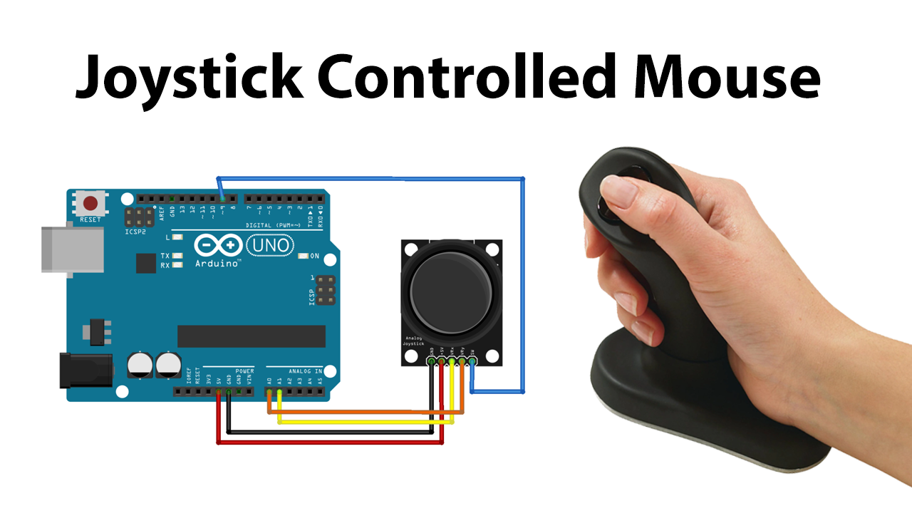
It’s likely that you’ve used a joystick a lot while playing your favorite game, or at the least, have seen someone else use one. .  But have you ever used a mouse-controlled joystick? If not, don’t worry, because in this post we’ll show you how to construct a Joystick Controlled Mouse with Arduino.

As you know. A joystick is a device that allows you to control the movement of the character you play in a video game and has a stick that goes left, right, forward, and backward as well as a sensor that determines where the stick is in relation to the screen. But, do you know what is joystick controlled mouse? Let’s discuss it!

What is Joystick Controlled Mouse?

Joystick-controlled mouse control is a device that controls the computer pointer when a button is pressed. This may be an alternate option for individuals who have trouble using a mouse. The device can move the cursor in any direction (x and Y axis) and also performs a click function with the built-in joystick’s switch.

Project description

Basics-

A joystick plainly consists of 2 potentiometers aligned in the x and y direction. The arduino reads analog values from the joystick in the range of 0 to 1023. Thus, when the joystick is in its default(center) position, the analog value also becomes close to 500(between 0 and 1023).

Source- lastminuteengineers.com


The arduino sketch is programmed such that when the joystick is moved away from the center, then print values in the range from -sensitivity to +sensitivity value(default vlaue set is 10) depending on the position. So, when the joystick is moved in one extreme position, the arduino prints value 10 and if the joystick is moved in other extreme position, then -10 is printed.

To print separate values for x and y direction, we will use ":" between the x and y direction values. Example:

Data printed by Arduino on the serial monitor


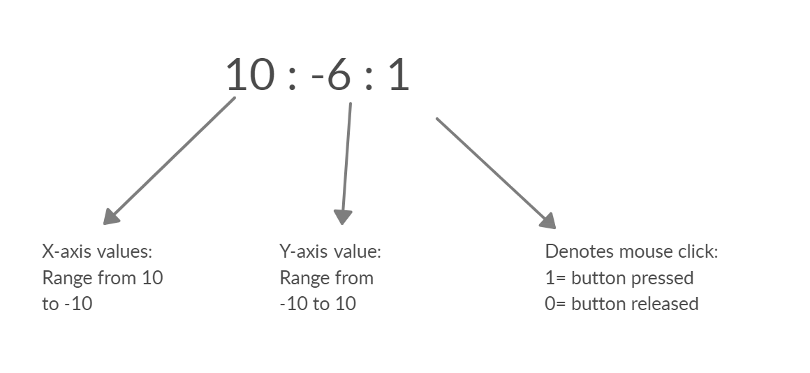
The status of joystick button(SW) is printed(1/0) on the serial monitor after the x and y values.

For the laptop/computer to recognize the values, we will need the python's pyautogui module.

Python Programming

(edited 12/11/2020 - changed the library from 'pyautogui' to 'mouse')

The user must have python 3 installed on their laptop/computer. It can be downloaded from the here.

After installation, Copy the path of the python file location.

copy the path of python3.8


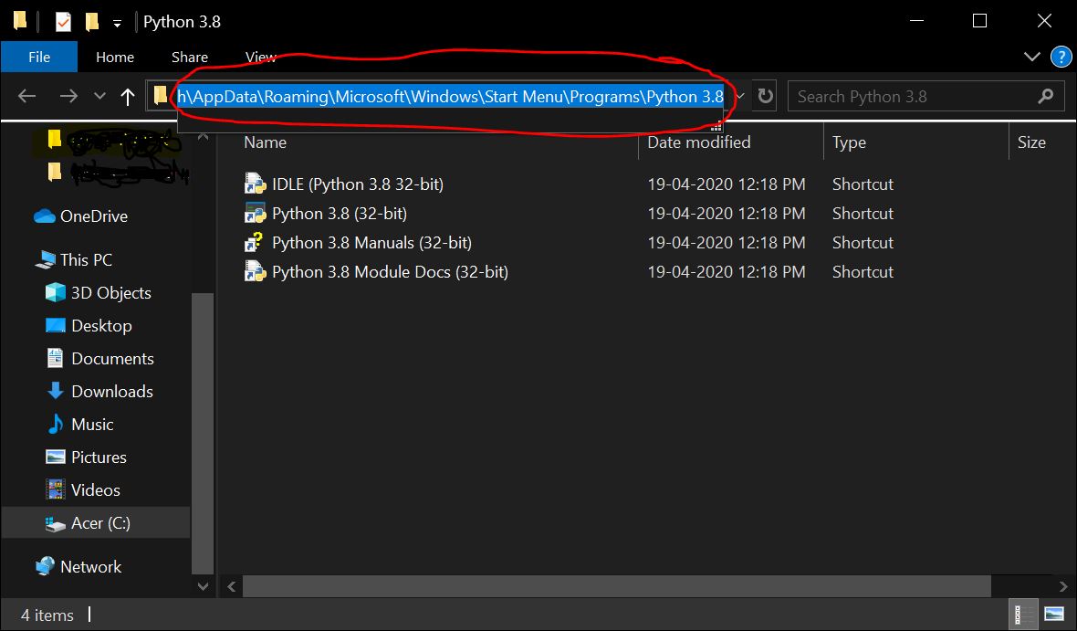
The following steps are to be performed on the command prompt. Open command prompt and enter the following-

1. cd

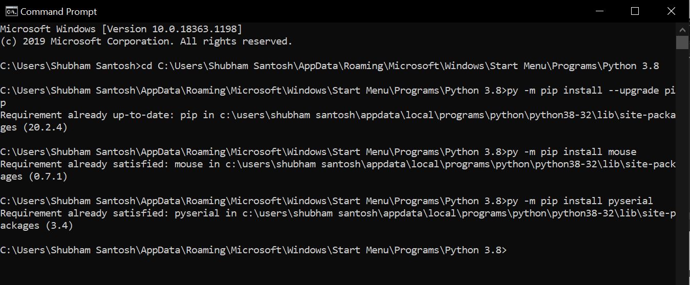
2. py –m pip install –-upgrade pip

3. py –m pip install mouse

4. py -m pip install pyserial

The mouse module is used to perform mouse action and pyserial module is used to send/receive data from the arduino. I had already installed the necessary modules, so I got this


The python program is made to read the data printed by the Arduino and recognise the x and y direction values as well as the status of switch(SW).

The current coordinates of the cursor is obtained from the mouse function mouse.get_position() which provides the cursor's X and Y co-ordinates in the form of pixels.

When the joystick is moved, the analog values provided by the arduino is added with the current cursor's position to move the cursor in the desired direction.

To move the cursor in the given direction, the function mouse.move(X+x,Y+y) satisfies this purpose.

where X and Y is the current cursor's position and x and y are the increment/decrement positions provided by the arduino.

example: mouse.moveTo(100,150) moves the cursor to 100 pixels in the x-axis and 150 pixels in the y-axis.

To perform click operation based on the SW status, mouse.click(button="left") is used.

Final Execution

Upload the arduino sketch(given below) to your arduino UNO and connect the joystick to the arduino pins as given in the schematic.

After ensuring that mouse and pyserial is installed on your computer/laptop perform the following steps.

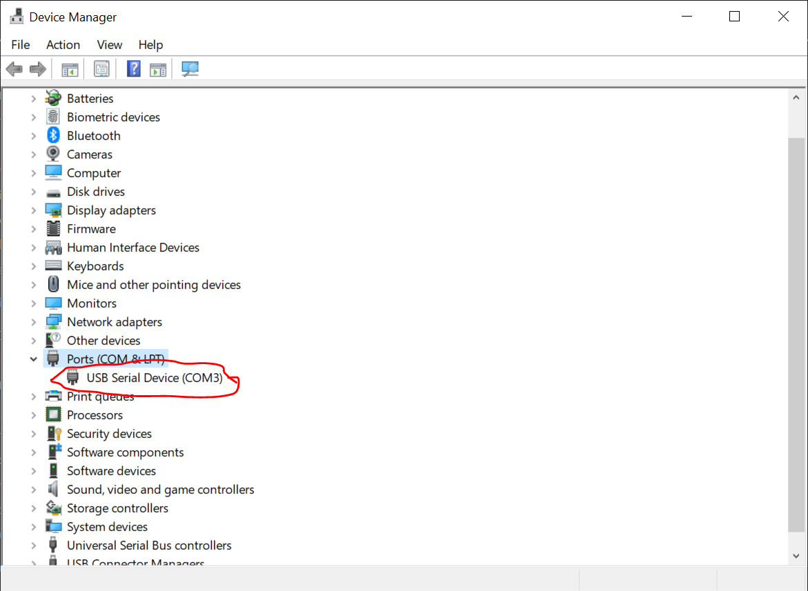
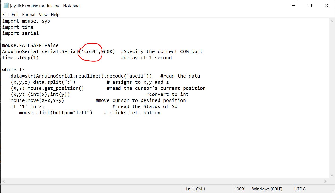
1. Copy the python sketch in a notepad file. Specify the correct COM port of the arduino. From the device manager, you can get the COM port to which the arduino board is connected. Save the file as ".py" after making changes.

(Fig 1)Check the COM port


(Fig 2) Enter the correct COM port


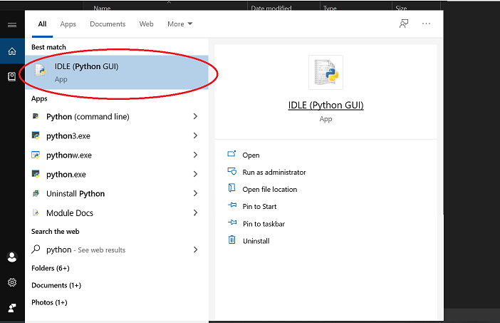
2. Open python's IDLE(python GUI) and open notepad file from it.
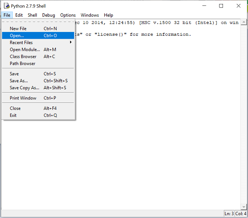
(Fig 3)open python interpreter (IDLE app)


(Fig 4)open the notepad file


3. run the module.


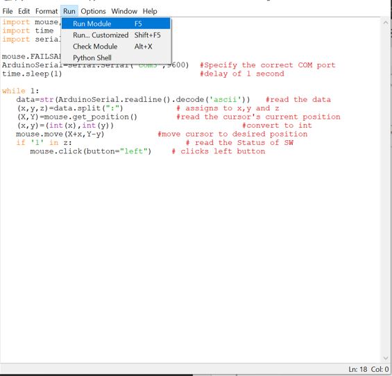
You will then be directed back to screen in Fig 4

In case you see any errors, restart the IDLE and check whether you have mentioned the correct COM port of the arduino.

If there are no errors, then move the joystick and you will see the movement of the cursor.


Code

Python Code

# Joystick controlled mouse

# By Shubham Santosh

# last edited 12/11/2020

import   mouse, sys

import time 

import serial


mouse.FAILSAFE=False

ArduinoSerial=serial.Serial('com3',9600)   #Specify the correct COM port

time.sleep(1)                             #delay   of 1 second


while 1:

   data=str(ArduinoSerial.readline().decode('ascii'))    #read the data

   (x,y,z)=data.split(":")           # assigns to x,y and   z

   (X,Y)=mouse.get_position()        #read the cursor's current position

    (x,y)=(int(x),int(y))                           #convert to int

   mouse.move(X+x,Y-y)            #move cursor to desired position

   if '1' in z:                        #   read the Status of SW

      mouse.click(button="left")    # clicks left button

    VIDERO


Comments

popular posts

AX2358 Homemade 5.1 Remote Kit with 16x2 LCD

AX2358 Homemade 5.1 Remote Kit with 16x2 LCD                                               AX2358 is I used for this 5.1 remote kit project. It is Built-in 2-channel to 6-channel converter and 6-channel volume controller. It has 4 stereo inputs and one 6 channel input. Any stereo input terminals of AX2358 are selected, it will be directly converted to 6 channels and then output through volume adjustment but when the signal from the 6-channel input terminal is selected, it directly enters the volume adjustment and then outputs it without any processing. It has 6-channel individual volume control in this IC (0 to -79dB, 1dB/step). This IC working by I2C communication. The data are transmitted to the AX2358 via the SDA and SCL. So I need a microcontroller. I choose the microcontroller is Atmega328 for this. This microcontroller programmed with Arduino UNO.      ...

DIY Tutorial Resetting Toner Chip on Ricoh SP C250DN Printer in Simple Steps

  DIY Tutorial Resetting Toner Chip on Ricoh SP C250DN Printer in Simple Steps The RICOH SP 250DN printer toners have a chip that keeps track of the number of pages that have been printed. This is anoying because it will render a refill useless. In order to reuse this kind of toner, there are two things you need to do: refill the toner with ink (if needed) reset the toner chip (or replace it) There is plenty of information explaining how to refill the toner but little information on how to erase the toner chip. This document deals with the second point: how to dump the chip and reset it. It took me a while to get everything setup and to have my toner chip reset so I would like to share this process in order to help other to do the same with their printer toner cartridges. I will step through the process of understanding the problem, analysing the chip circuit, dumping the chip contents and writing back a pattern so the printer will be able to initialize the chip and set t...

DIY Metal Detector using Arduino A Simple Guide to Building Your Own at Home

  DIY Metal Detector using Arduino A Simple Guide to Building Your Own at Home How does a metal detector work? As we can see there are three things that are using to complete the whole project. Electronic circuit, Arduino, and a copper coil. here actually we are making a proximity sensor that detects the metal with a  metal detector  using Arduino . Here are the steps to build a DIY metal detector using an Arduino: Materials required: Arduino UNO Copper coil Diode 10nf capacitor Buzzer Led 220 ohm &  330 Ohm Resistor Jumper wires and a breadboard USB cable for uploading the code Circuit Diagram Arduino metal detector:-  Arduino UNO 10 nf Capacitor A2 Pin Terminal 1 GND Terminal 2 Arduino UNO Buzzer D6 Pin Positive GND  Negative Arduino LED 220 Ohm Resistor D5 Pin   Terminal 1   Anode Pin Terminal 2 GND Cathode Pin   Arduino UNO Copper coil Diode 330-ohm res   Terminal 1 Terminal 1 Terminal 1 A1 Pin     Terminal 2 A2 Pin ...

How to Calculate Inverter Battery Backup Time

  How to Calculate Inverter Battery Backup Time? Backup Time (in hours) = Battery Capacity (in Ah) X Input voltage (V) / Total Load (in Watts) Whenever you plan to buy an inverter battery, there is a desire to know some important information in your mind. Like how much will be the backup of the inverter battery, how many hours of backup will be available for how many ah batteries, etc. In this informative information, here you will know the backup time calculation formula.   Taking your inputs, you can calculate your total load, like: 3 tube led lights = 40 x 3 = 120 Watts 2 fans = 75 x 2 = 150 Watts 1 Bulb router = 1×20 Watts = 20 Watts So, the total load in your case is 120 + 150 + 20 = 290 Watts. Now, let us apply all these values in the above-said battery backup time formula.  Backup Time (in hours) = Battery Capacity (in Ah) X Input voltage (V) / Total Load (in Watts) Backup Time (in hours) = 150 x 12 / 290 = 6.2 So, your inverter battery will last around 6.2 hours ....

Wireless Joystick controlled Robot Car using Arduino, 433Mhz RF and L298N Motor Driver

    Wireless Joystick controlled Robot Car using Arduino – In this tutorial, you will learn how to control a Robot Car wirelessly using Arduino, L298N Motor driver, and  433 Mhz RF transmitter and Receiver . The robot control system can be activated and de-activated using the Built-in Joystick push Button. Arduino Uno Arduino Nano Mega 2560: Robot Car chassis kit: L298N motor driver: 2-Axis Analog Joystick 433 MHz Transmitter and Receiver Modules: DISCLAIMER: Please Note: these are affiliate links. I may make a commission if you buy the components through these links. I would appreciate your support in this way! wireless joystick Interfacing: Watch this tutorial for the robot parts assembling and connections. All the connections are exactly the same as explained in my previous tutorial. The only modification that I did is the addition of the 433 Mhz RF receiver module…the VCC pin of the receiver module is connected with the 5 volts…the ground pin of the ...