
Pi_Camera
Nowadays people are paying their attention to work with Single Board Computers (SBCs) for their projects rather than using large computers or bunch of micro-controllers inside a limited space. There are several reasons behind this. These SBCs are highly integrated circuit boards with many kinds of microprocessors, memory chips, GPIO (Input/output) features with different communication protocols and etc. within a small single printed circuit board. Considerably high computational power with essential external interfacing I/O features and low power consumption makes these kinds of circuits are ideal for robotics, IoT, Machine learning and many other portable applications. Here we are going to work on a considerably advanced project using a Raspberry Pi SBC which I was implemented as a sub part of one of my university projects.
Therefore, in this blog post I am discussing about setting up a Raspberry Pi computer and use it for a useful and interesting project related to basic robotics and many embedded systems.
Setting Up Raspberry Pi Step1: Here we are going to flash Raspbian operating System to a Raspberry Pi SBC. I used a Raspberry Pi 3 Model B platform and a 16GB microSD card for the process. For our application any available version of RPi will be okay and at least 8GB microSD card is required. There are two steps to install Raspbian in to Raspberry pi.
-
1. You need to download latest Raspbian image file to your computer from official website. (The latest version is Raspbian Buster July 2019 is for this date) I recommend to download ‘Raspbian Buster with desktop and recommended software’ option from the following link since there is a valuable software pack in it. After download the image file, write it to your microSD using ‘Win32DiskImager’ software.
Link: https://www.raspberrypi.org/downloads/raspbian/
-
2. Online Installing process with NOOBS which is an easy operating system installer.
Link: https://www.raspberrypi.org/downloads/noobs/
Step2: After successfully installing Raspbian into your microSD card plug it into your RPi and connect a Display through HDMI port, a USB mouse, a Keyboard and finally a 5V 2.5A micro USB power supply. It will boot up after several seconds with an initialization process.
After a successful bootup to the Raspbian desktop, you have to do several configuration setups to enable camera interface.
Open up a terminal window and enter following command to enable camera interface.
$ sudo raspi-config
This will open a new configuration interface with several options. You need to go the ‘Interfacing options’. There you will see several interfaces like SPI, VNC, Camera, SSH, I2C, Serial and Remote GPIO. Enable Camera interface and SSH(Secure Shell interface) from the above list. Here we enabled SSH of RPi in order to remotely access to our Pi from a computer. We will cover enabling camera step in the following topic.
Interfacing the Pi Camera
Now we are going to work with Raspberry Pi camera. In different models of RPi computers there is a dedicated socket for interfacing a camera. You need to connect the Pi camera to the Camera interface of your Raspberry Pi through the ribbon cable connector carefully as the following picture.
Now make sure you enable the Camera interface on your pi following below steps.
Open a terminal and type
$sudo raspi-config
It will open the raspberry pi configuration window with several kinds of settings. You need to navigate through the menu using arrow keys to the Interfacing Options and select it by hitting enter.
Then, enable the camera interface as you see in the following screen shot.
Finally, finish configuration by saving the settings. It will ask to reboot your pi while quitting. Hit "yes".
After successfully interfacing the camera to the RPi you can play with several python scripts which are related to Pi camera including taking photo stills, Videos, sequence of stills, and some other interesting activities which can be important for your projects. I am not going to go through these codes. You can find these basic scripts in the link below..
https://github.com/ChandulaNethmal/Pi_Camera/tree/master/Pi_cam
Now we need to connect our raspberry pi to a local are network (i.e. through Wifi or Ethernet) selecting available connections. Not only the Pi, the computer which you are going to use to watch the live video also must be connected to the same local area network.(i.e. to the same wifi hotspot).
Live Streaming with Pi Camera Here we are focusing on transmitting a video stream capturing from the pi camera to a computer or mobile phone via a local network in real-time.
First of all, let’s take a look at the python Script. Following is the first part of the code which is creating the web interface to the live stream receiver side.
PAGE="""\
<title>Raspberry Pi - Live Stream</title>Raspberry Pi - Live Stream

"""
Here we are taking the stream in to a web page according to the above HTML formatting. Title of the page is “Raspberry Pi – Live Stream” as you can see in the fourth row. We are taking the source of stills sequence from the code which is defined as “stream.mpeg”, which is having a width of 640 pixels and height of 480 pixels in the center of the window.
class StreamingOutput(object):
def __init__(self):

    self.frame = None

    self.buffer = io.BytesIO()

    self.condition = Condition()


def write(self, buf):

    if buf.startswith(b'\xff\xd8'):

        self.buffer.truncate()

        with self.condition:

            self.frame = self.buffer.getvalue()

            self.condition.notify_all()

        self.buffer.seek(0)

    return self.buffer.write(buf)
Let’s define a python class called “StreamingOutput” containing two functions for initializing and writing the buffered frames.
Other than the above class, we are defining several other classes as StreamingHandler and StreamingServer. In the streaming handler we are maintaining the live stream with HTTP requests and image data sending. Streaming Server will keep the server function in the network and maintain the threading.
with picamera.PiCamera(resolution='640x480', framerate=24) as camera:
output = StreamingOutput()

#Uncomment the next line to change your Pi's Camera rotation (in degrees)

#camera.rotation = 90

camera.start_recording(output, format='mjpeg')

try:

    address = ('', 8000)

    server = StreamingServer(address, StreamingHandler)

    server.serve_forever()

finally:


    camera.stop_recording()
Finally, we have the main code which is continuously running. Here we are defining the resolution and frame rate of each frame at the beginning as “640x480” and “24fps”. You can change these two parameters according to your needs, but there are some limitations in the setup. Processing power of both RPi and Camera cause limitation of FPS and resolution. Even if the quality will increase with the resolution, it causes higher delays between frames depending on the LAN(WiFi) connectivity strength. Then we are defining the streaming server address as “IPV4_address_of _ur_pi,port”. Here we define our port as “8000” and the IPV4 address will depend on your local network and it will automatically assign.
You can download the full Python Script from this link.
https://github.com/ChandulaNethmal/Pi_Camera/tree/master/Live_streaming
Now we are going to run the code on the Raspberry pi node through the Raspberry pi Terminal.
You will see something like following screenshot after that.
Congrtulations!.............You have successfully deployed the live streaming server.
Now we need to access to that server through another computer/mobile phone using a web browser. Open your web browser from a laptop or desktop computer or mobile phone while keep running the camera stream of our previous setup. In the web browser enter the following address in the URL typing bar according to your” Rpi_ipv4_address:Port” as the following example of mine.
192.168.1.4:8080
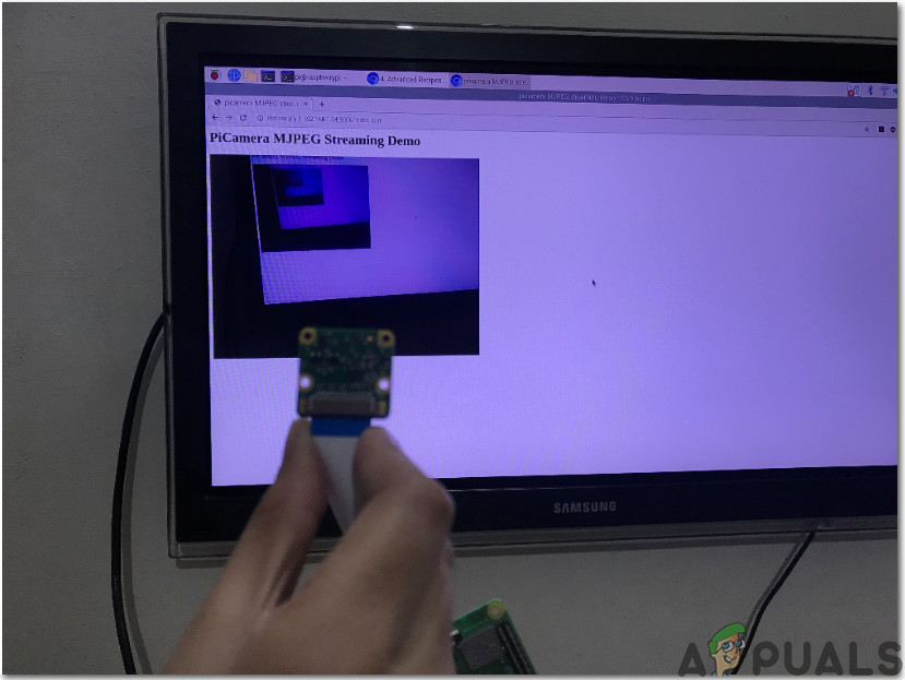
It will bring the web page we created in the very first of the python code and the live video frames from your PI Camera as follows.
Now we have successfully deployed our project with the pi camera. You can use this setup in various projects such as a surveillance system with RPi, teleoperating robots and so on. Also you can change basic setting of the video in the python scripts and adjust the stream according to your requirements.
Video linkL
Comments
Post a Comment