

Robots are playing an important role in automation across all the sectors like construction, military, medical, manufacturing, etc. After making some basic robots like line follower robot, computer controlled robot, etc, we have developed this accelerometer based gesture controlled robot by using arduino uno. In this project we have used hand motion to drive the robot. For this purpose we have used accelerometer which works on acceleration.
Required Components
- Arduino UNO
- DC Motors
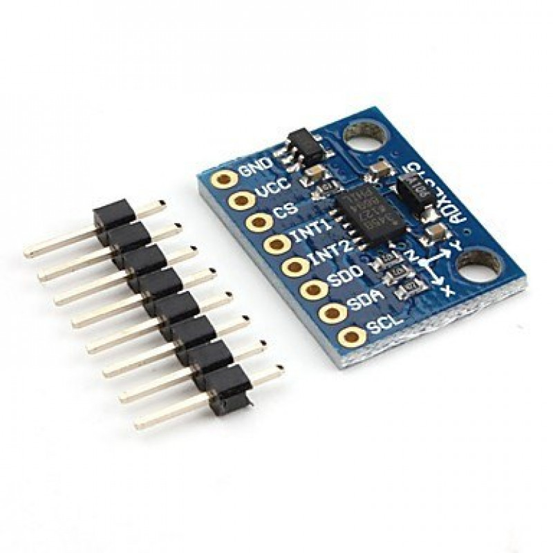
- Accelerometer
- HT12D
- HT12E
- RF Pair
- Motor Driver L293D
- 9 Volt Battery
- Battery Connector
- USB cable
- Robot Chasis
RF Pair:
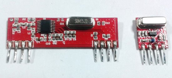
A gesture controlled robot is controlled by using hand in place of any other method like buttons or joystick. Here one only needs to move hand to control the robot. A transmitting device is used in your hand which contains RF Transmitter and accelero-meter. This will transmit command to robot so that it can do the required task like moving forward, reverse, turning left, turning right and stop. All these tasks will be performed by using hand gesture.
Here the most important component is accelerometer. Accelerometer is a 3 axis acceleration measurement device with +-3g range. This device is made by using polysilicon surface sensor and signal conditioning circuit to measure acceleration. The output of this device is Analog in nature and proportional to the acceleration. This device measures the static acceleration of gravity when we tilt it. And gives an result in form of motion or vibration.
According to the datasheet of ADXL345 polysilicon surface-micromachined structure placed on top of silicon wafer. Polysilicon springs suspend the structure over the surface of the wafer and provide a resistance against acceleration forces. Deflection of the structure is measured using a differential capacitor which incorporate independent fixed plates and plates attached to the moving mass. The fixed plates are driven by 180° out-of-phase square waves. Acceleration deflects the moving mass and unbalances the differential capacitor resulting in a sensor output whose amplitude is proportional to acceleration. Phase-sensitive demodulation techniques are then used to determine the magnitude and direction of the acceleration.
Circuit Diagram and Explanation
Gesture Controlled Robot is divided into two sections:
- Transmitter part
- Receiver part
In transmitter part an accelerometer and a RF transmitter unit is used. As we have already discussed that accelerometer gives an analog output so here we need to convert this analog data in to digital. For this purpose we have used 4 channel comparator circuit in place of any ADC. By setting reference voltage we gets a digital signal and then apply this signal to HT12E encoder to encode data or converting it into serial form and then send this data by using RF transmitter into the environment.
At the receiver end we have used RF receiver to receive data and then applied to HT12D decoder. This decoder IC converts received serial data to parallel and then read by using arduino. According to received data we drive robot by using two DC motor in forward, reverse, left, right and stop direction.
Working
Gesture controlled robot moves according to hand movement as we place transmitter in our hand. When we tilt hand in front side, robot start to moving forward and continues moving forward until next command is given.
When we tilt hand in backward side, robot change its state and start moving in backwards direction until other command is given.
When we tilt it in left side Robot get turn left till next command.
When we tilt hand in right side robot turned to right.
And for stopping robot we keeps hand in stable.
Circuit Diagram for Transmitter Section
Receiver

Circuit Diagram for Receiver Section
Circuit for this hand gesture controlled robot is quite simple. As shown in above schematic diagrams, a RF pair is used for communication and connected with arduino. Motor driver is connected to arduino to run the robot. Motor driver’s input pin 2, 7, 10 and 15 is connected to arduino digital pin number 6, 5, 4 and 3 respectively. Here we have used two DC motors to drive robot in which one motor is connected at output pin of motor driver 3 and 6 and another motor is connected at 11 and 14. A 9 volt Battery is also used to power the motor driver for driving motors.
Comments
Post a Comment