
Easy DIY Metal Touch Sensor with Arduino for School Projects 100% Working:
KY-036 Metal touch sensor Module Arduino:
KY-036 Metal touch sensor Module with Arduino– In this article, we will learn how to use the KY-036 metal touch sensor Module and its use with the Arduino Uno or Arduino Nano. The KY-036 metal touch sensor module features a Darlington and PN transistor, the signal of which is controlled by LM393 comparator IC which consists of two comparators. When you touch the bar wire meant over the transistor which is represented by the base of the transistor.
The 50 Hertz signal around us in a modern home or office is injected into a high gain amplifier the output of this amplifier is connected to the comparator. The AC signal is then converted to the square wave. We can adjust the sensitivity of the sensor by adjusting the trimmer. When we will touch the sensor the led will starts blinking. If you look closely at the led you will see a slight flicker this is due to the output that is represented by a square wave of 50 Hertz instead of constant value.
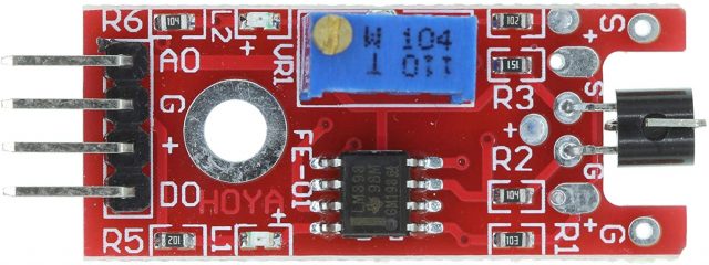
This module has integrated on board touch sensor which consists of potentiometer one microchip, six resistors and two LEDs. The resistor R1 used in this module is10-kilo ohms the resistor R2 is 100-kilo ohms the resistor R3 is 150 ohms and the resistor R4 is 1-kilo ohm the resistor R5 is 1-kilo ohm the resistor R6 is 100-kilo ohms and the main reason for using the resistors is to limit current circulating inside the module in other words to prevent current from burning the module. The LED L1 in the module lights up to show if the module is working properly or not and the LED L2 lights up every time when we touch the sensor.
Features of the KY-036 touch sensor:
These are some features of the sensor:
- It has a power supply 3.3 volt or 5.5 volt.
- its sensitivity is adjustable
- it has an analog and digital output
- Packaging: antistatic sealed bag
- Form dimensions 34 x 16 mm
There are two built-in LEDs on the sensor module. The LED1 shows that the sensor is supplied with voltage and the LED2 will show that the sensor is detecting magnetic field. The main component of the KY-036 Metal Touch sensor module on its circuit board is the sensor unit at the front of the module which measures the area physically and send an analog signal to the second unit, the amplifier. The amplifier amplifies the signal according to the resistors value of the potentiometer and send the signal to the analog output of the Metal Touch Sensor module. The third component is a comparator which switch the digital output and the LED. If the signal falls under a specific value you can control the sensitivity by adjusting the potentiometer, here please note the signal will be inverted that may that if you measure a higher level high value it is shown as a low-voltage value at the analog output. The sensor does not show absolute value it is a relative measurements you define an extreme value to a given normal environment situation and a signal will be sent if the measurement exceeds the extreme value.
Working Principle of the KY-036:
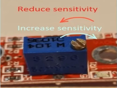
Let us quickly understand the working principle of the KY-036 Metal Touch sensor module. Basically, the functionality of the KY-036 Metal Touch sensor module is divided into three main components first the sensor unit at the front of the module which measures the area physically and sends an analog signal to the second unit the amplifier. The amplifier basically amplifies the signal and according to the resistance value of the potentiometer and sends the signal to the analog output of the module also you can set the sensitivity of the sensor by adjusting the knob of the potentiometer. If you rotate it in clockwise direction you can increase the sensitivity and if you rotate it in anti-clockwise direction you can reduce the sensitivity as shown in the diagram.
The comparator will switches the digital out and turn on the led if the signal falls under a specific value.
KY-036 Pinout:
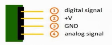
It has basically four pins digital signal, VCC +V, Ground, and analog signal.
Interfacing KY-06 with Arduino, Circuit:
We will be using digital signal pin, the VCC pin, and the ground of the sensor to interface it with Arduino.
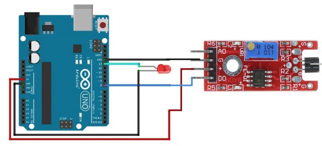
This is the circuit diagram for the KY-036 Metal Touch sensor module interface with the Arduino. We are going to connect the ground pin with the ground of the Arduino. The VCC of the sensor will be connected with the 5V of the Arduino. The digital pin of the sensor will be connected with the digital pin number 8 of the Arduino. Connect the led with pin number 13 of the Arduino I am using a 5v led, if you are using a standard 2.5 LED then don’t forget to add a resistor of 330 ohms with the LED, otherwise the LED will burnout.
KY-036 Metal Touch sensor Arduino Code:
So, if you go ahead and upload this code, you will be able to control the LED. This is just a basic program to check if it is really working.
KY-036 touch sensor with Arduino and Relay module:
Now we will connect the touch KY-036 Touch Sensor with Arduino and relay module and when we touch the sensor bulb will turn on and in this way we can control home appliances and turn it on and off by just touching the sensor.
Components Required:
- KY-036 touch sensor
- Arduino UNO
- Relay module
- Bulb
KY-036 Circuit connection:
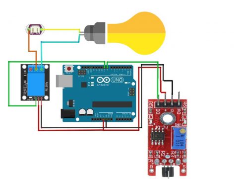
- Connect the ground pin of the KY-036 touch sensor with the ground of the Arduino
- Connect the VCC of the touch sensor with the 5 V of the Arduino
- Connect the touch sensor Vo at the digital pin 8
- Connect the relay module at the digital pin number D9
- Connect the ground of the relay module with the ground of the Arduino
- Connect 5V supply to the relay module
- Connect the normally open contact of the relay module with the bulb
- Connect the other normally closed of the relay module with the switch
- Connect the other terminal of the switch with the bulb
Now the circuit is completed and after uploading the code when we will touch the sensor the bulb will be on.
KY-036 touch sensor Arduino Code to control a Bulb:
Comments
Post a Comment