Getting Started with Arduino and PIR Sensors for Home Security: An Easy Guide to Implementing Motion Detection with Code

Getting Started with Arduino and PIR Sensors for Home Security: An Easy Guide to Implementing Motion Detection with Code

Detecting motions or movements has always been important in most projects. With the help of the PIR Sensor it has become very easy to detect human/animal movements. In this project we will learn how we can interface a PIR Sensor with a microcontroller like Arduino. We will interface an Arduino with PIR module and blink a LED and beep a Buzzer whenever a movement is detected. The following components will be needed to build this project.
Materials Required:
- PIR Sensor Module
- Arduino UNO (any version)
- LED
- Buzzer
- Breadboard
- Connecting Wires
- 330 ohm resistor
PIR sensor:
The PIR sensor stands for Passive Infrared sensor. It is a low cost sensor which can detect the presence of Human beings or animals. There are two important materials present in the sensor one is the pyroelectric crystal which can detect the heat signatures from a living organism (humans/animals) and the other is a Fresnel lenses which can widen the range of the sensor. Also the PIR sensor modules provide us some options to adjust the working of the sensor as shown in below image.


The two potentiometers (orange color) are used to control the sensitivity and trigger on time of the sensor. Basically the Dout pin of the sensor is present in between the Vcc and Gnd pins. The module works on 3.3V but can be powered with 5V as well. On the top left corner it also has a trigger pin setup which can be used to make the module work in two different modes. One is the “H” mode and the other is the “I” mode.
In “H” mode the output pin dout will go high (3.3V) when a person is detected within range and goes low after a particular time (time is set by potentiometer). In this mode the output pin will go high irrespective of whether the person is still present inside the range or has left the area. We are using our module in “H” mode in our project.
In “I” mode the output pin dout will go high (3.3V) when a person is detected within range and will stay high as long as he/she stays within the limit of the Sensors range. Once the person has left the area the pin will go low after the particular time which can be set using the potentiometer.
Note: The position of potentiometers or pins may vary based on your PIR sensor vendor. Follow the Silk screen to determine you pinouts
Circuit Diagram and Explanation:
The circuit Diagram for Arduino motion detector project by interfacing Arduino with PIR module and blinking an LED/Buzzer is shown in the below image.

We have powered the PIR sensor using he 5V Rail of the Arduino. The output pin of the PIR Sensor is connected to the 2nd digital pin of Arduino. This pin will be the INPUT pin for Arduino. Then the 3rd pin of Arduino is connected to the LED and Buzzer. This pin will act as the output pin of the Arduino. We will program the Arduino to trigger an Output on 3rd pin if an Input has been detected at 2nd pin. The complete Program is explained below.
Programming the Arduino:
The program for Arduino is pretty simple and straight forward. To connect Arduino PIR Sensor, we have to assign the pin number 2 as input and pin number 3 as output. Then we have to produce a discontinuous trigger whenever the pin 2 goes high. Each line is explained below.
In the void setup function shown below, we have to declare that the pin 2 connected to PIR output will be used as input and the pin 3 connected to LED/Buzzer will be used as input.
void setup() {

  pinMode(2, INPUT); //Pin 2 as INPUT

  pinMode(3, OUTPUT); //PIN 3 as OUTPUT

}
Then we proceed to the loop() function. As we know the code in here gets executed as long as the MCU is powered on. So we always check if the Pin 2 has gone high by using the below line inside the loop() function.
if (digitalRead(2) == HIGH)If we find that the particular pin has gone high, it means that the PIR module has be triggered. So, now we has make our output pin (pin 3) to go high. We turn this pin on and off with a delay of 100 milli second so that we can attain the flashing or buzzing output. The code to do the same is shown below.
void setup() {

  pinMode(2, INPUT); //Pin 2 as INPUT

  pinMode(3, OUTPUT); //PIN 3 as OUTPUT

}


void loop() {

  if (digitalRead(2) == HIGH) // check if PIR is triggered.

  {

  digitalWrite(3, HIGH);   // turn the LED/Buzz ON

  delay(100);                       // wait for 100 msecond

  digitalWrite(3, LOW);   // turn the LED/Buzz OFF

  delay(100);                       // wait for 100 msecond

  }

}
Working:
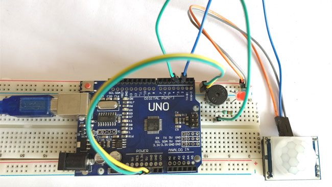
The circuit and program for this Arduino motion detector project is already discussed above. Now, you can build this circuit on a breadboard by following the schematics given above and upload the program which could found at the end of this tutorial. Once your connections are done your set-up should look like something shown below.
Now, power on the Arduino and wait for about 50-60 seconds for your PIR sensor to calibrate. Do not be frustrated by the output that you get during this period. After that, try moving in front of the PIR sensor and you LED/Buzzer should be triggered as shown in the video below.
The beeping/flashing should stop after some time; you can now toy around the output by varying the potentiometer to change the sensitivity or the low time of the module. Hope you understood the project and got it working, if you have any trouble in getting this thing work, you can search out through the comment section or on our forums.
void setup() {
pinMode(2, INPUT); //Pin 2 as INPUT
pinMode(3, OUTPUT); //PIN 3 as OUTPUT
}void loop() {
if (digitalRead(2) == HIGH)
{
digitalWrite(3, HIGH); // turn the LED/Buzz ON
delay(100); // wait for 100 msecond
digitalWrite(3, LOW); // turn the LED/Buzz OFF
delay(100); // wait for 100 msecond
}
}
Comments
Post a Comment