
Building a Home Automation System with an Arduino Board and Sensors

Home Automation: Using an Arduino board and various sensors, you can create a system to control lights, temperature, and other aspects of your home.


Yes, that's correct. You can use an Arduino board and various sensors to create a home automation system that can control lights, temperature, and other aspects of your home. This can be done by connecting the Arduino board to various devices such as lights, thermostats, and appliances, and using sensors to detect changes in temperature, motion, and other environmental factors.

Arduino IR Remote control circuit to control Relay module Arduino Projects for Home Automation

Here are some examples of how you can use an Arduino board and sensors to create a home

automation system:

1.Smart lighting: You can use an Arduino board and a light sensor to automatically turn lights on and off based on the ambient light level in a room.

2.Temperature control: You can use an Arduino board and a temperature sensor to control the temperature in a room by adjusting the thermostat or activating a cooling/heating system.

3.Smart door lock: You can use an Arduino board and a fingerprint sensor to create a smart door lock that can be unlocked using fingerprints.

4.Energy monitoring: You can use an Arduino board and energy monitoring sensors to track the energy consumption of your home and identify ways to reduce energy usage.

5.Security system: You can use an Arduino board and motion sensors to create a security system that can detect intruders and trigger an alarm.

These are just a few examples of the many ways you can use an Arduino board and sensors to create a home automation system. The specific components and coding will depend on the specific project you have in mind.

Home Automation Using an Arduino board and control lights and fan using IR Remote:
Here is a sample program code that uses an Arduino board, a remote control receiver and two relays to control a light and a fan:

#include <IRremote.h>

int RECV_PIN = 11;
int relay1 = 8;
int relay2 = 9;

IRrecv irrecv(RECV_PIN);
decode_results results;

void setup() {
  pinMode(relay1, OUTPUT);
  pinMode(relay2, OUTPUT);
  digitalWrite(relay1, LOW);
  digitalWrite(relay2, LOW);
  irrecv.enableIRIn();
  Serial.begin(9600);
}

void loop() {
  if (irrecv.decode(&results)) {
    switch(results.value) {
      case 0xA90: //code for button "light on" on remote
        digitalWrite(relay1, HIGH);
        Serial.println("Light on");
        break;
      case 0xA91: //code for button "light off" on remote
        digitalWrite(relay1, LOW);
        Serial.println("Light off");
        break;
      case 0xA92: //code for button "fan on" on remote
        digitalWrite(relay2, HIGH);
        Serial.println("Fan on");
        break;
      case 0xA93: //code for button "fan off" on remote
        digitalWrite(relay2, LOW);
        Serial.println("Fan off");
        break;
    }
    irrecv.resume();
  }
}

Note: The above code snippet is an example and it is assuming that you have the IRremote library installed and the remote buttons have been configured to emit the specific IR code (0xA90, 0xA91, 0xA92, 0xA93) that is used in the code. Also, make sure to use the correct pin number for the receiver and relay.

Arduino IR Remote control circuit to control Relay module | Arduino Projects for Home Automation


To control a light and a fan using an Arduino board, a remote control receiver, and two relays, you would need to wire the remote control receiver to the Arduino board to receive signals from the remote. Then, you would need to wire the two relays to the Arduino board and connect them to the light and fan, respectively. Finally, you would need to write code in the Arduino programming language that interprets the signals received from the remote and uses them to control the state of the relays, turning the light and fan on and off as desired.

Working Explanation:

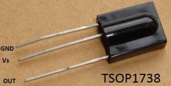
Working of this project is easily understandable. When we press any button of IR Remote then remote sends a code in form of train of encoded pulses using 38Khz modulating frequency. These pulses are received by TSOP1738 sensor and read by Arduino and then Arduino decodes received train of pulse into a hex value and compares that decoded value with the predefined hex value of the pressed button. If any match occurs then Arduino perform relative operation and the corresponding result is also displayed on 16x2 LCD by using appropriate commands. Here in this project we have used 3 bulbs of different colors, for demonstration which indicates Fan, Light and TV.

There are many types of IR Remote are available for different device but most of them are worked on around 38KHz Frequency signal. Here in this project we control home appliances using IR TV remote. For detecting IR remote signal, we use TSOP1738 IR Receiver. This TSOP1738 sensor can sense 38Khz Frequency signal. The working of IR remote and the TSOP1738 can be covered in detail in this article: IR Transmitter and Receiver

TSOP1738

Components: 

  • Arduino UNO
  • IR TV/DVD Remote
  • ULN2003
  • Relays 5 volt
  • Bulb with holder
  • Connecting wires
  • Bread board
  • Power supply

Here in this project we have used  8 and 9,11 number button of IR remote, for controlling Fan, Light and TV respectively and ON/OFF button (Power button) is used for turning ON and OFF all the appliances simultaneously.

Here we have used toggle [EVEN ODD] method for ON and OFF the single home appliance. Toggle method is nothing but to get that whether the button is pressed even no of times or the odd no of times. This is found by getting the reminder after dividing it by 2 (i%2), if there is some reminder then device will be turned ON and if reminder is 0 then it will be turned OFF. Suppose Key 11 is pressed on the remote then remote sends a signal to Arduino through TSOP IR Receiver. Then Arduino decode it and store the decoded value into the results variable. Now results variable has a hex value 0x1FE00FF, after matching it with the predefined hex value of key 7 (see above image), Arduino turns ON the Fan. Now when we press the same key (key 7) again then IR sends the same code. Arduino gets same code and matched with same code like before but this time Fan turned OFF because of toggling the bit [EVEN ODD] (i%2). 

Decoding IR Remote Control Signals using Arduino:

Here is a list of a DVD NEC type Remote decoded output codes:

IR Remote and Hex codes


If you don’t know the Decoded output for your IR remote, it can be easily found, just follow these steps:

  1. Download the IR remote library from here https://github.com/z3t0/Arduino-IRremote.
  2. Unzip it, and place it in your Arduino ‘Libraries’ folder. Then rename the extracted folder to IRremote.
  3. Run the below program from your Arduino and open the Serial Monitor window in Arduino IDE. Now press any IR Remote button and see the corresponding decoded hex output in Serial Monitor window.

Arduino IR Remote control circuit to control Relay module | Arduino Projects for Home Automation

Comments

popular posts

AX2358 Homemade 5.1 Remote Kit with 16x2 LCD

AX2358 Homemade 5.1 Remote Kit with 16x2 LCD                                               AX2358 is I used for this 5.1 remote kit project. It is Built-in 2-channel to 6-channel converter and 6-channel volume controller. It has 4 stereo inputs and one 6 channel input. Any stereo input terminals of AX2358 are selected, it will be directly converted to 6 channels and then output through volume adjustment but when the signal from the 6-channel input terminal is selected, it directly enters the volume adjustment and then outputs it without any processing. It has 6-channel individual volume control in this IC (0 to -79dB, 1dB/step). This IC working by I2C communication. The data are transmitted to the AX2358 via the SDA and SCL. So I need a microcontroller. I choose the microcontroller is Atmega328 for this. This microcontroller programmed with Arduino UNO.      ...

DIY Tutorial Resetting Toner Chip on Ricoh SP C250DN Printer in Simple Steps

  DIY Tutorial Resetting Toner Chip on Ricoh SP C250DN Printer in Simple Steps The RICOH SP 250DN printer toners have a chip that keeps track of the number of pages that have been printed. This is anoying because it will render a refill useless. In order to reuse this kind of toner, there are two things you need to do: refill the toner with ink (if needed) reset the toner chip (or replace it) There is plenty of information explaining how to refill the toner but little information on how to erase the toner chip. This document deals with the second point: how to dump the chip and reset it. It took me a while to get everything setup and to have my toner chip reset so I would like to share this process in order to help other to do the same with their printer toner cartridges. I will step through the process of understanding the problem, analysing the chip circuit, dumping the chip contents and writing back a pattern so the printer will be able to initialize the chip and set t...

DIY Metal Detector using Arduino A Simple Guide to Building Your Own at Home

  DIY Metal Detector using Arduino A Simple Guide to Building Your Own at Home How does a metal detector work? As we can see there are three things that are using to complete the whole project. Electronic circuit, Arduino, and a copper coil. here actually we are making a proximity sensor that detects the metal with a  metal detector  using Arduino . Here are the steps to build a DIY metal detector using an Arduino: Materials required: Arduino UNO Copper coil Diode 10nf capacitor Buzzer Led 220 ohm &  330 Ohm Resistor Jumper wires and a breadboard USB cable for uploading the code Circuit Diagram Arduino metal detector:-  Arduino UNO 10 nf Capacitor A2 Pin Terminal 1 GND Terminal 2 Arduino UNO Buzzer D6 Pin Positive GND  Negative Arduino LED 220 Ohm Resistor D5 Pin   Terminal 1   Anode Pin Terminal 2 GND Cathode Pin   Arduino UNO Copper coil Diode 330-ohm res   Terminal 1 Terminal 1 Terminal 1 A1 Pin     Terminal 2 A2 Pin ...

How to Calculate Inverter Battery Backup Time

  How to Calculate Inverter Battery Backup Time? Backup Time (in hours) = Battery Capacity (in Ah) X Input voltage (V) / Total Load (in Watts) Whenever you plan to buy an inverter battery, there is a desire to know some important information in your mind. Like how much will be the backup of the inverter battery, how many hours of backup will be available for how many ah batteries, etc. In this informative information, here you will know the backup time calculation formula.   Taking your inputs, you can calculate your total load, like: 3 tube led lights = 40 x 3 = 120 Watts 2 fans = 75 x 2 = 150 Watts 1 Bulb router = 1×20 Watts = 20 Watts So, the total load in your case is 120 + 150 + 20 = 290 Watts. Now, let us apply all these values in the above-said battery backup time formula.  Backup Time (in hours) = Battery Capacity (in Ah) X Input voltage (V) / Total Load (in Watts) Backup Time (in hours) = 150 x 12 / 290 = 6.2 So, your inverter battery will last around 6.2 hours ....

Wireless Joystick controlled Robot Car using Arduino, 433Mhz RF and L298N Motor Driver

    Wireless Joystick controlled Robot Car using Arduino – In this tutorial, you will learn how to control a Robot Car wirelessly using Arduino, L298N Motor driver, and  433 Mhz RF transmitter and Receiver . The robot control system can be activated and de-activated using the Built-in Joystick push Button. Arduino Uno Arduino Nano Mega 2560: Robot Car chassis kit: L298N motor driver: 2-Axis Analog Joystick 433 MHz Transmitter and Receiver Modules: DISCLAIMER: Please Note: these are affiliate links. I may make a commission if you buy the components through these links. I would appreciate your support in this way! wireless joystick Interfacing: Watch this tutorial for the robot parts assembling and connections. All the connections are exactly the same as explained in my previous tutorial. The only modification that I did is the addition of the 433 Mhz RF receiver module…the VCC pin of the receiver module is connected with the 5 volts…the ground pin of the ...